
This is a description of how to set up the ACK project from PATB files. This description does not use ProjectSetup. Strips are defined manually. For larger projects ProjectSetup is preferred. PATB measurements will be imported rather than EO data. I have found it to be more reliable.
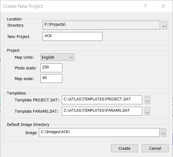
Define the Project. Nothing special here.
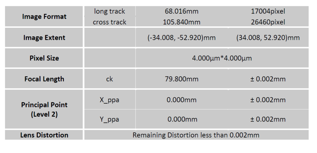
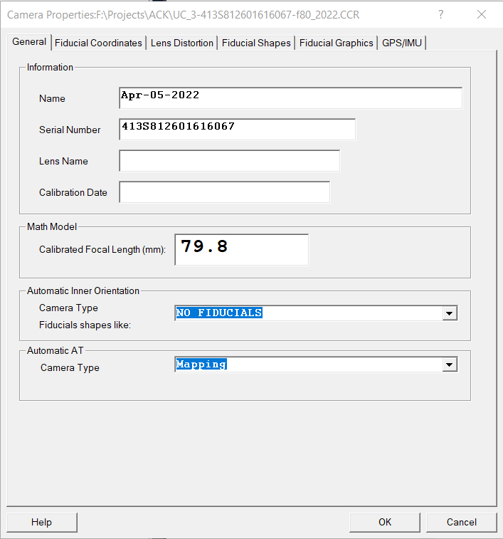
Setup the camera file. This project uses an Ultracam Eagle with no principal point offset.
KLT prefers a View/Photo rotation of 0 degrees or 180 degrees. With this project and most digital image projects, the images are in landscape mode rather than portrait mode. KLT prefers portrait mode, and that is how this project will be defined.
Below are images of the camera calibration report information and the camera definition.
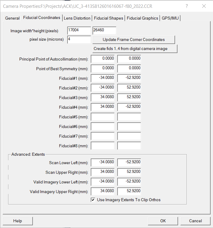
As you can see the image height and width values are swapped, which alters the V/P rotation to Portrait mode when the V/P rotation is 0 or 180 degrees. With a V/P rotation of 0 degrees, fiducial number 1 will be at the lower left corner, or upper right for V/P rotation of 180 degrees.
The camera for this project does not have a Principal Point offset so V/P rotation of 0 could be used for all the flight lines. If the Principal Point is not zero, then V/P rotation is critical. Additionally the Principal Point values will need to be altered because the V/P rotation has been changed from landscape to portrait.
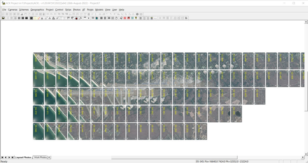
Since the images do not indicate a strip number, we need to determine how the images are organized into strips. This is where ProjectSetup could be extremely helpful.
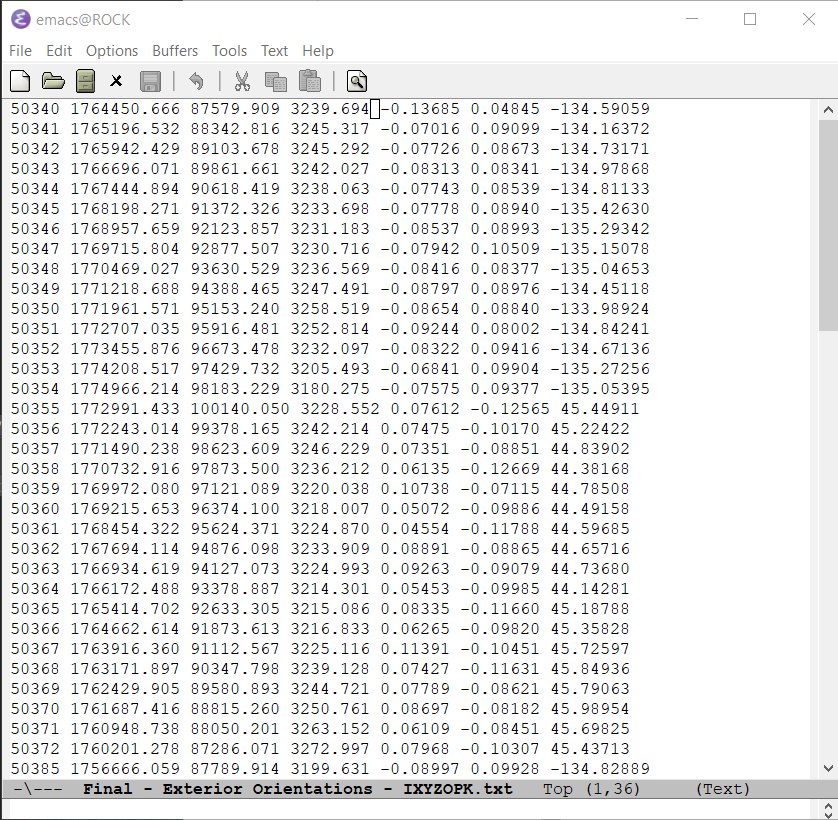
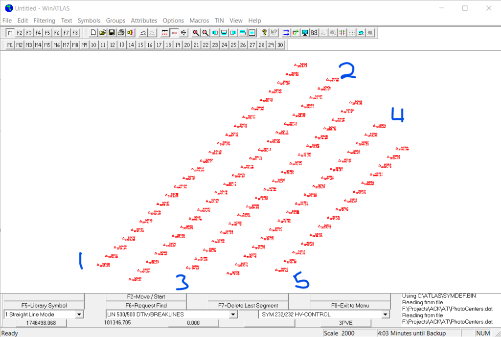
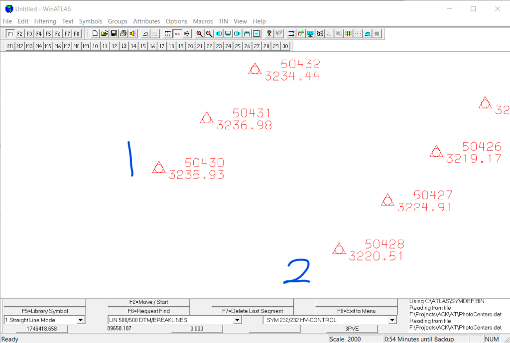
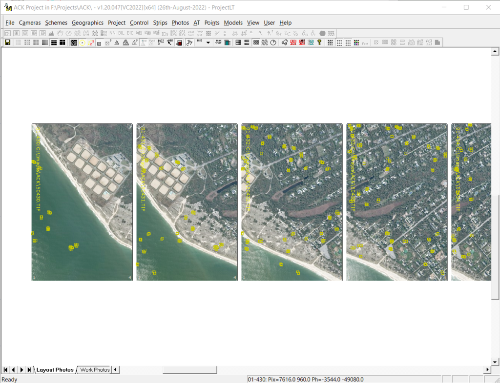
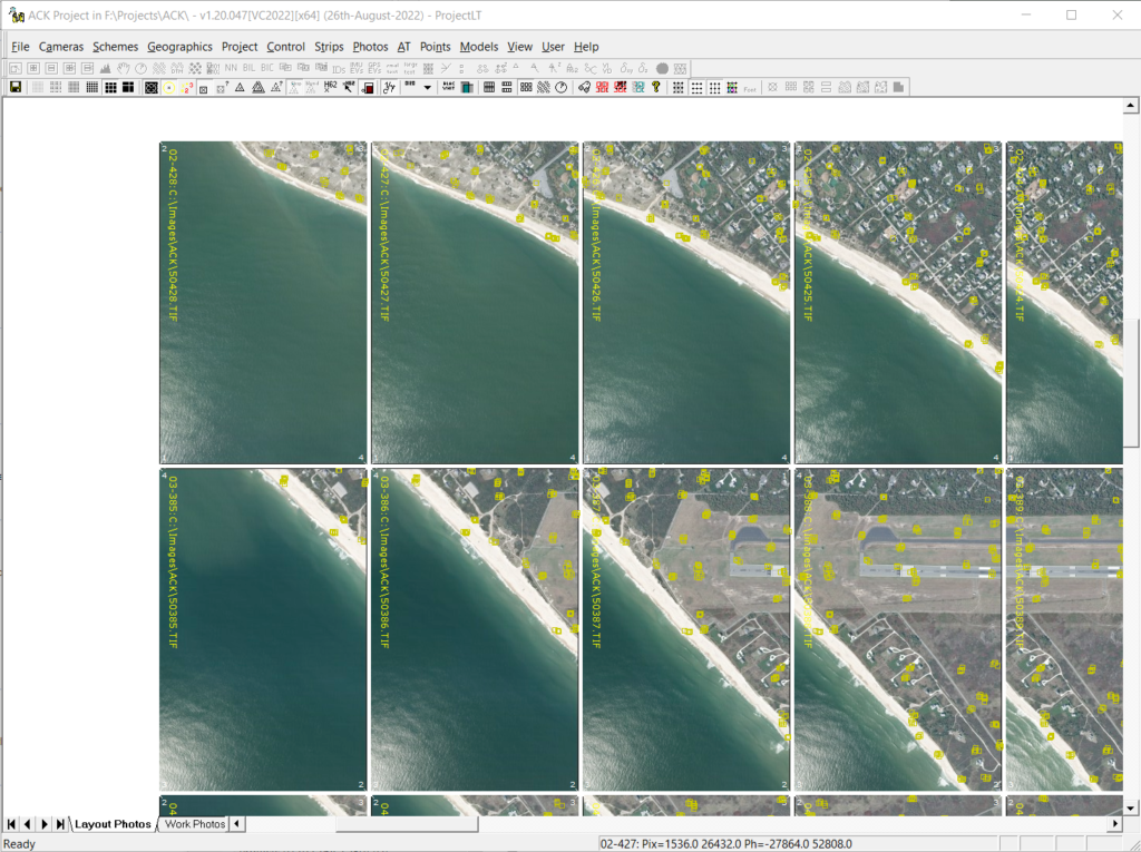
The ‘Final – Exterior Orientations.txt’ file can be used to view the photo centers in WinAtlas, to determine the images in each strip. Open WinAtlas (with no data) and set the map scale to 2000, Attributes>Map_Scale. Import the photo centers using File>Import>Load_Ground_Control. Change the extension to ‘All Files (*.*)’ in the Extension pull down at the lower right corner of the dialog box and specify the Final – Exterior Orientations.txt file. Click F4 to load all points. One note about Load_Ground_Control. The last line must end in a carriage return or the last line will not be imported. The last line of the EO file, as provided, ends without a carriage return.
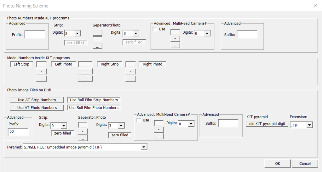
Specifying the schemes for the project. There is no strip number in the filenames so the standard scheme needs to be altered to make the strip definition faster.
Determine the rotations for the strip 1. Strip 1, 3, and 5 will have the same rotations. Strip 2 and 4 will have the same rotations, 180 degrees from strips 1, 3, and 5.
Define only strip 1 with a View/Photo rotation of 0. We will use strip 1 to check the V/P rotation.

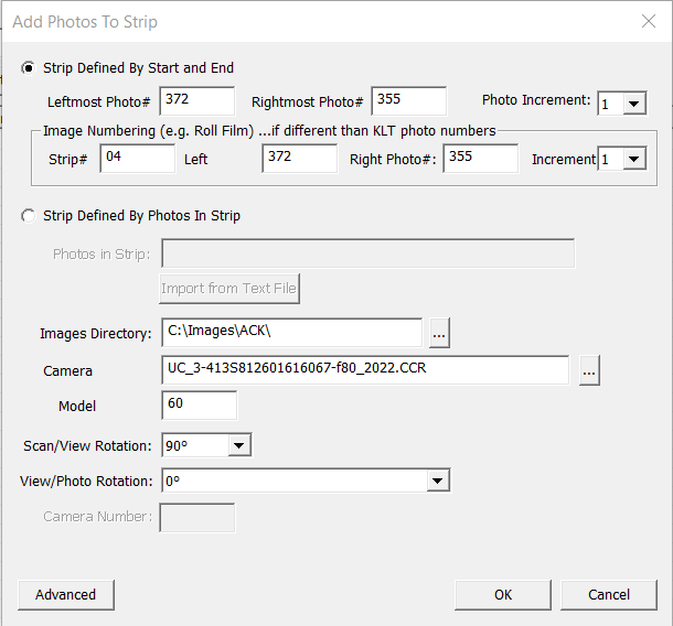
Define the remaining strips.
The direction of flight for the odd strips is from left to right and the even strips are right to left.
The odd strips have a S/V rotation of 270 degrees and a V/P rotation of 180 degrees.
The even strips have a S/V rotation of 90 degrees and a V/P rotation of 0 degrees.


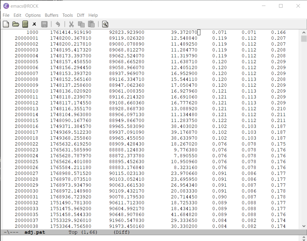
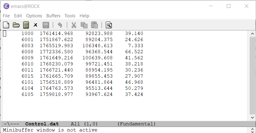
The ADJ.PAT file contains the ground coords for all the points in the project, pass points and control. The difference between the ADJ.PAT file and the standard KLT Ground.dat file is the last 3 columns. Ground.dat has two columns, indicating on or off for horizontal or vertical. ADJ.PAT appears to have the standard deviation numbers for x, y , and z. I strip off the last three columns of the ADJ.PAT using the Linux cut command.
cut -c -70 <adj.pat >ground.dat.
70 characters works for this file, probably not for some others. This step may not be necessary. I am not sure what KLT will do in this situation. Place the Ground.dat file in the project directory.
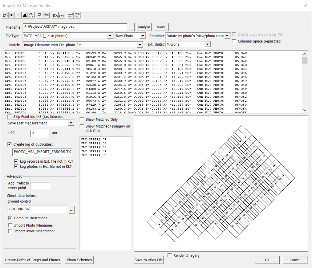
Time to import the pass points and control. This information is in the image.pat file.
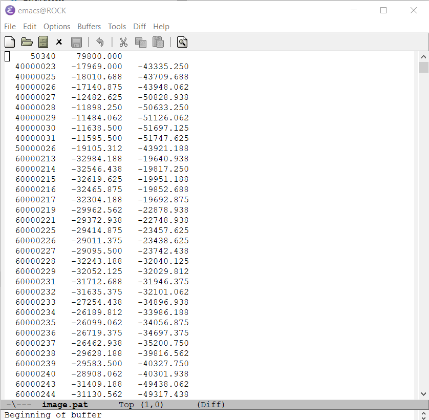
Note the rotation box at the upper right. Rotating by V/P rotation is the most common in my experience.
Extract the control measurements from the PATB exported file cont.pat.
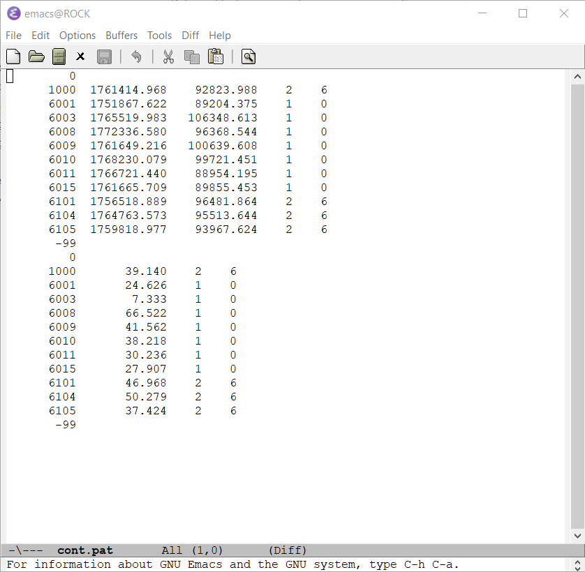
That’s it.